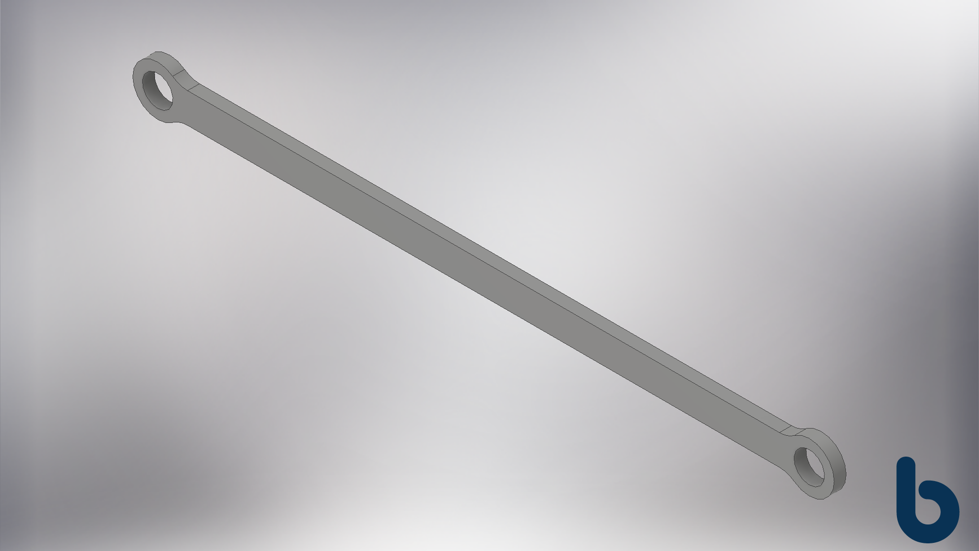
Finally got the big bed printing! One of the next steps is to replace the Delta Rod End Arms with Arms w/ Ball Bearings.
Basic, First Design. I don't have much experience with long thin printed parts, so I'm starting with a very simple design. 217mm center to center with a 10mm x 4mm shaft cross section.
1st Test Rod Arm Printed
Finished Part off the Printer
Press Fit in the 623ZZ Bearings. These are 3mm ID X 10mm OD x 4mm THK.
These are interference fit, but the modeled hole is Ø10.2mm due to printed holes being slightly smaller.
Printed Arm Installed. I'm surprised it has so much play. If I had to guess, it's about 1/4th the stiffness of the original carbon fiber rod.
Need to look into how to print a more rigid structure.
Checking the Stiffness of the New Arm and Effector.
My notepad entry immediately after: Expected it to be Stiffer, not sure if better or worse that Delta Rod Arm.
Edit: This is the 2 Wall arm.
Figured out why the arm was so flexible: Cura was only slicing with 2 walls instead of 4. It appears to be some bug in how I configured the Deltesian as a custom machine. I created a new machine type in Cura, set it as a Delta Kossel Mini and then set the bed size to 200x420mm and Cura sliced the model with 4 walls as intended.
The 4 walls are important b/c (1) the holes for the bearing are designed to be solid plastic when printed, i.e. no infill & (2) those layers are what give the arm beam stiffness, like an I-Beam.
FEA testing in Inventor
I need to get a better idea on some of the failure modes of a shape like this arm so I running some analysis of the arm under different loading conditions.
It's Important to note:
- I'm using small load conditions to understand which design element is the weak link.
- I'm not validating a design here. I don't know enough to call this anything other than my first best guess. I'm the kid taking apart his toys trying to understand how they work.
- I'm only showing the Load Condition and Von Mises Stress images. I have full readout...400 pages of it, not exactly page scrolling stuff.
- If you know more about FEA and plastic/printed plastic deformation, please let me know, I'm probably missing something.
Cantilever Loading
Fixing the right bearing seat and loading the left shows a build up of stress near the shoulders on the right. This will never happen with the bearings mounted but its interesting to see.
Tensile Loading
Applying a Force pulling the two bearing seats apart, results in some interesting deformation in the left bearing seat. The only the right seat does not look like the left, b/c the software thinks it's fixed in place.
Out of Plane Loading
Applying a force out of plane--in relation to the Deltesian Effector--show stress concentrations near the right bearing seat. This sort of loading is possible with the Deltesian. I need to experiment and research some better ways to design the part to increase the strength and stiffness under these conditions.
torque loading
Applying a moment to the left bearing seat is interesting(?). I'm not exactly sure what to make of this other than: "Long Thin Thing Twists - More on that at 10." It's obvious in retrospect but had to check anyways.
2 Walls vs 4 Walls
2nd Printed Rod Arm with 4 Walls Installed.
This is where stuff gets weird. In the hand, it feels less stiff than the 2 wall version. It doesn't make sense, which is why I'm confused.
The really odd part happens when I attach the arm and see how it feels on the machine...
Watch the Effector (blue thing) when I try and *roll* it left to right. Its the last action in both clips.
I had to post the 1 New Arm vs 2 New Arm videos side by side so you can see what I felt, which I questioned if I was imagining things:
Swapping the 2 lower Rod End Arms out for the Roller Bearing Arms appears to have reduced whatever small amount of roll the Effector was free to do.
Typing this out it, I realize it seems obvious but I did not expect it to make that big a difference.
take aways
- Didn't expect the arms to stiffen the effector the way it did.
- I don't fully understand where the slop was that allowed the rolling motion.
- Need to test further the difference between 2vs4 walls. Apparently, I don't fully understand where thicker walls are beneficial.
- FEA gave me some ideas on how to modify the geometry to stiffen and reinforce things.
- Is the flex in the arms okay? Need to answer that.
Calling it quits at that. It's a lot to think about.
Personal note: I want to make this a thing, to keep myself documenting the process. I'm not diligent enough at these sort of things but I really enjoy it when I do it so, here's hoping.


